In Part 1 I discussed motivation and research where I decided to build a custom, open source wired solution. Part 2 discussed the prototype and other experiments.
Because we were having to fit in with the builder, I didn’t have enough time to finalise the smart system, so I needed a dumb mode. This Part 3 is about rolling out dumb mode in Smart house!
Operation “dumb mode, Smart house” begins
We had a proven prototype, now we had to translate that into a house-wide implementation.
First we designed and mapped out the cabling.
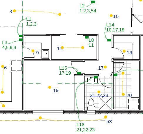
Cable ALL THE THINGS.
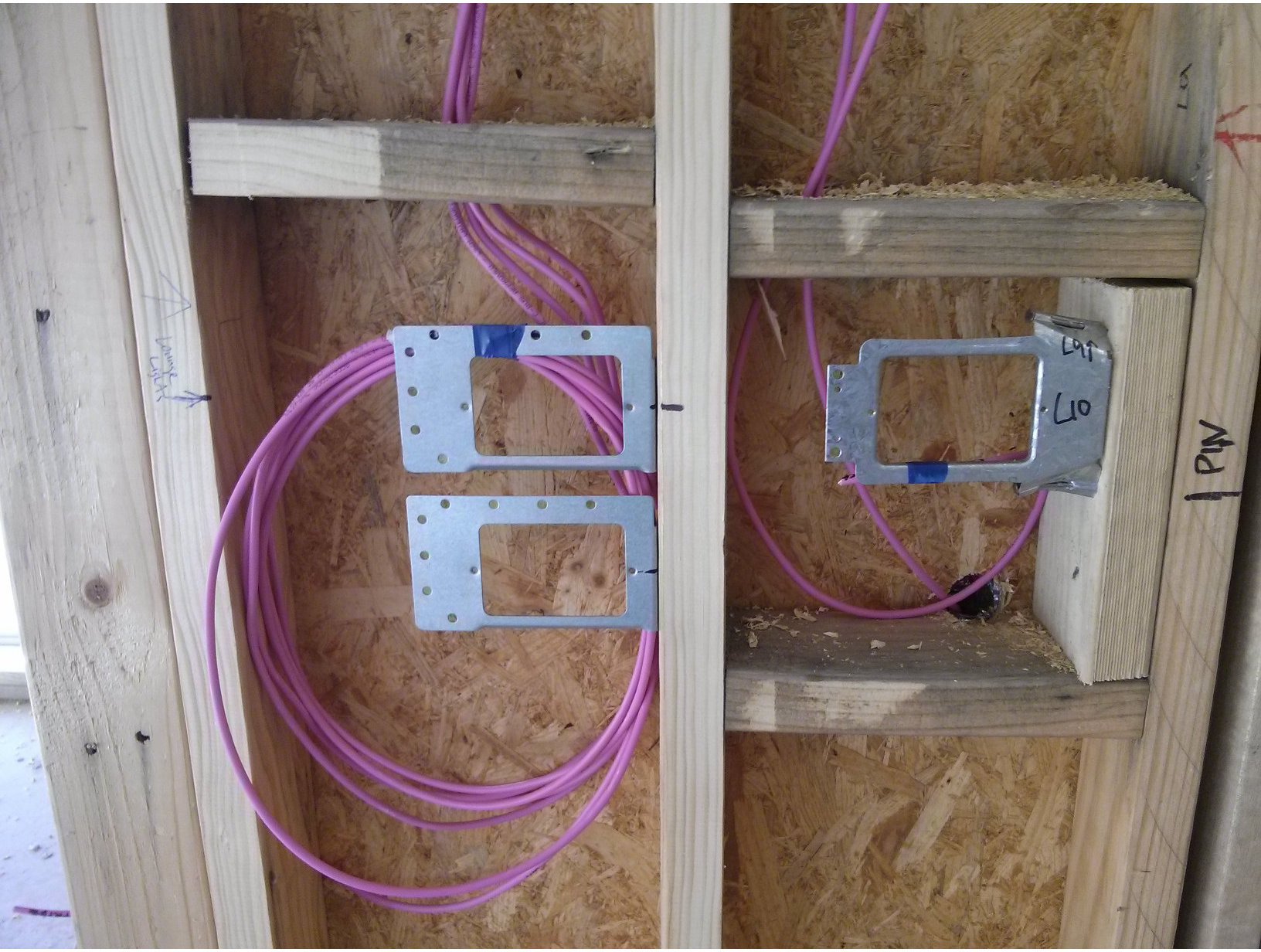
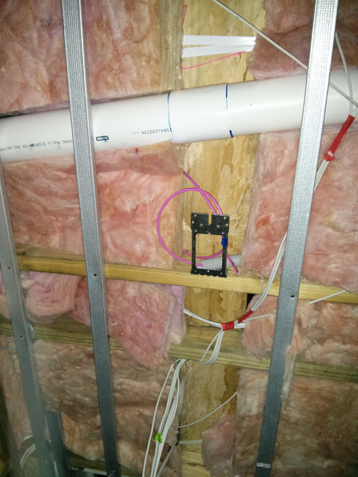
- Cat5e (sometimes multiple runs) for room Arduinos
- Cat5e to windows for future curtain motors
- Reed switch cables to light switch
- Regular Cat6 data cabling too, of course!
- Whatever else we thought we might need down the track
Time was tight (fitting in with the builder) but we got there (mostly).
- Ran almost 2 km of cable in total
- This was a LOT of work and took a LOT of time


Electrical cable
This is the electrician’s job.
- Electrician ran each bank of lights on their own circuit
- Multiple additional electrical circuits
- HA on its own electrical circuit, UPS backed
- Study/computers on own circuit, UPS backed
- Various others like dryer, ironing board, entertainment unit, alarm, ceiling fans, ovens, etc
- Can leave the house and turn everything off
(except essentials)
Relays
The relays had to be reliable, but also available off-the-shelf as I didn’t want to get something that’s custom or hard to replace. Again, for devices that draw too much current for the relay, it will throw a contactor instead so that the device can still be controlled.
- Went with Finder 39 series relays, specifically 39.31.0.024.0060
- Very thin profile
- Built in fuses
- Common bus bars
- Single Pole Double Throw (SPDT)
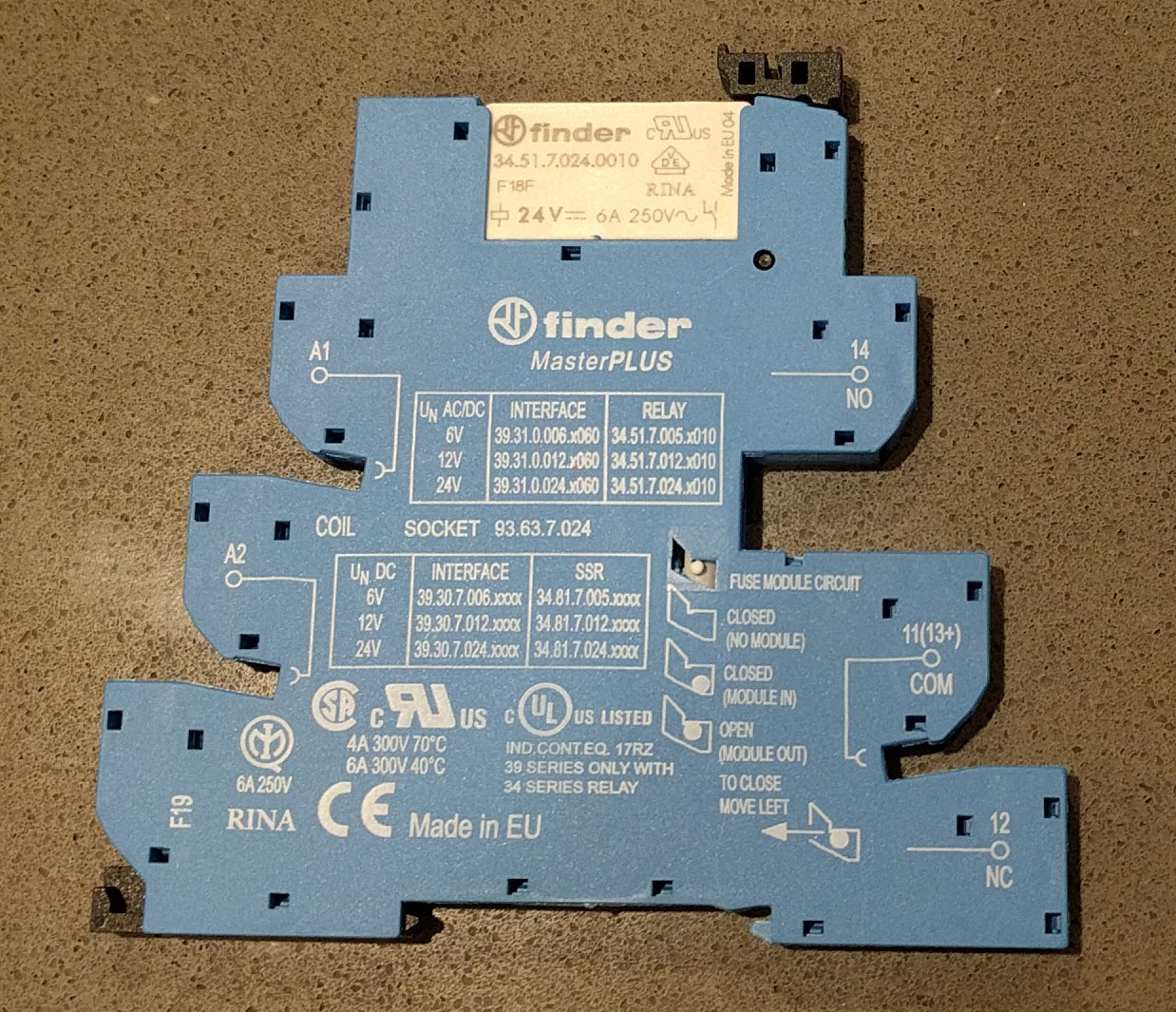
These are triggered by 24V DC which switches the 240V AC for the circuit. The light switches are running 24V and when you press the button it completes the circuit, providing 24V input to the relay (which turns on the 240V and therefore the light).
There are newer relays now which have an input range (e.g. 0-24V), I would probably use those instead if I was doing it again today so that it can be more easily fired from an array of outputs (not just a 24V relay driver shield).
The fact that they are SPDT means that I can set the relay to be normally open (NO) in which case the relay is off by default, or normally closed (NC) in which case the relay is on by default. This means that if the smart system goes down and can’t provide voltage to the input side of the relay, certain banks of lights (such as the hallway, stairs, kitchen, bathroom and garage lights) will turn on (so that the house is safe while I fix it).

In the photo above you can see the Cat5e 24V lines from the light switch circuits coming into the grey terminal block at the bottom. They are then cabled to the input side of the relays. This means that we don’t touch any AC and I can easily change what’s providing the input to the relay (to a relay board on an Arduino, for example).

There are two racks, one upstairs and one downstairs, that provide the infrastructure for the HA and data networks.
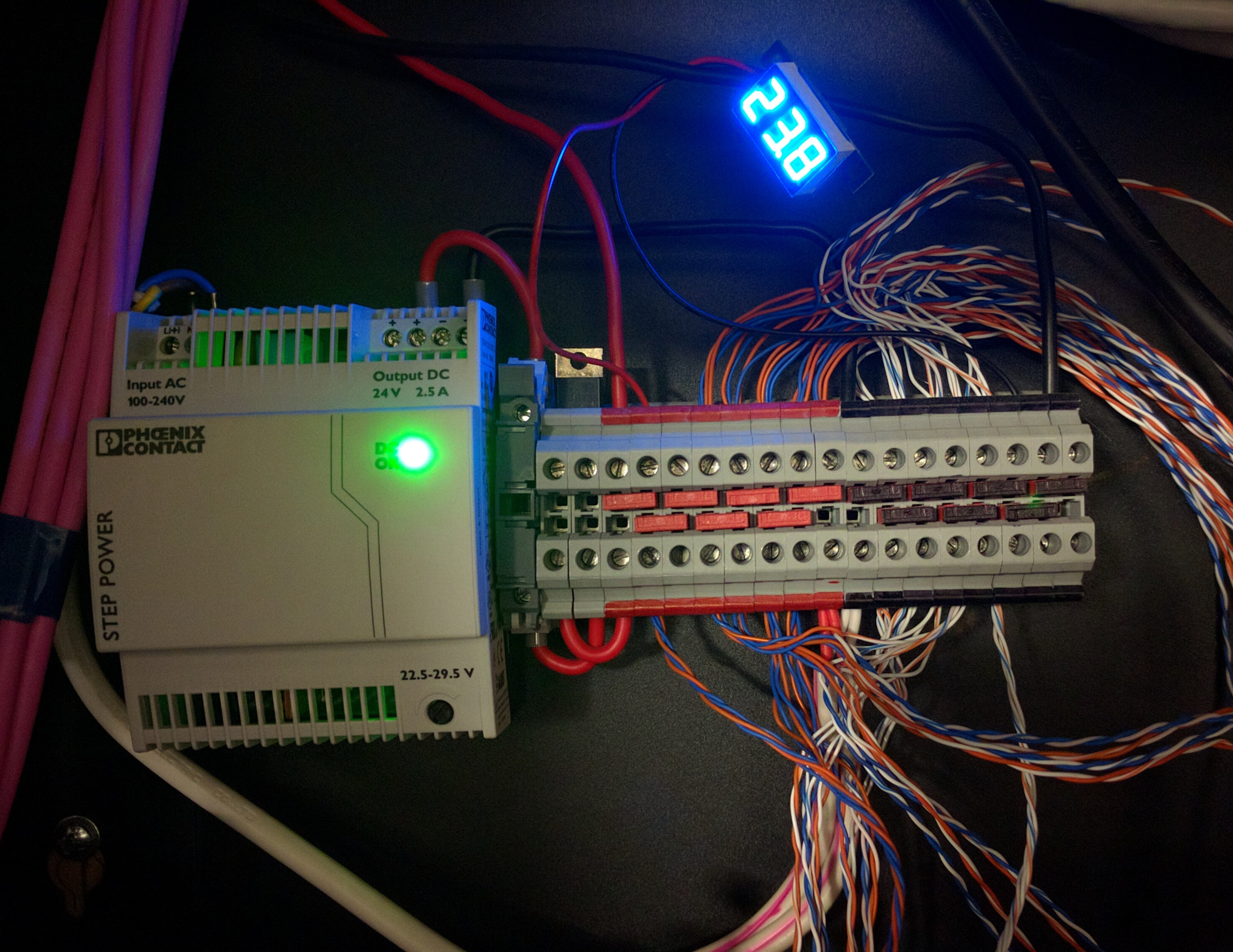
Each rack has a power supply unit (PSU) running at 24V which provides the power for the light switches in dumb mode. These are running in parallel to provide redundancy for the dumb network in case one dies.
You can see that there is very little voltage drop.
Relay Timers
The Finder relays also support timer modules, which is very handy for something that you want to automatically turn off after a certain (configurable) amount of time.
- Heated towel racks are bell press switches
- Uses a timer relay to auto turn off
- Modes and delay configurable via dip switches on relay
UPS backed GPO Circuits

Two GPO circuits are backed by UPS which I can simply plug in-line and feed back to the circuit. These are the HA network as well as the computer network. If the power is cut to the house, my HA will still have power (for a while) and the Internet connection will remain up.
Clearly I’ll have no lights if the power is cut, but I could power some emergency LED lighting strips from the UPS lines – that hasn’t been done yet though.
Switches
The switches for dumb mode are regular also off the shelf light switches.
- Playing with light switches (yay DC!)
- Cabling up the switches using standard Clipsal gear
- Single Cat5e cable can power up to 4 switches
- Support one, two, three and four way switches
- Bedroom switches use switch with LED (can see where the switch is at night)
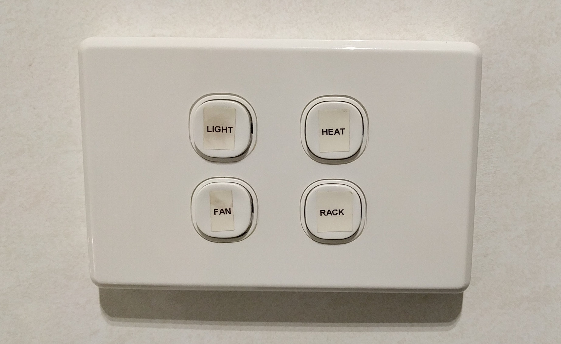
We have up to 4-way switches so you can turn a single light on or off from 4 locations. The entrance light is wired up this way, you can control it from:
- Front door
- Hallway near internal garage door
- Bottom of the stairs
- Top of the stairs
A single Cat5e cable can run up to 4 switches.
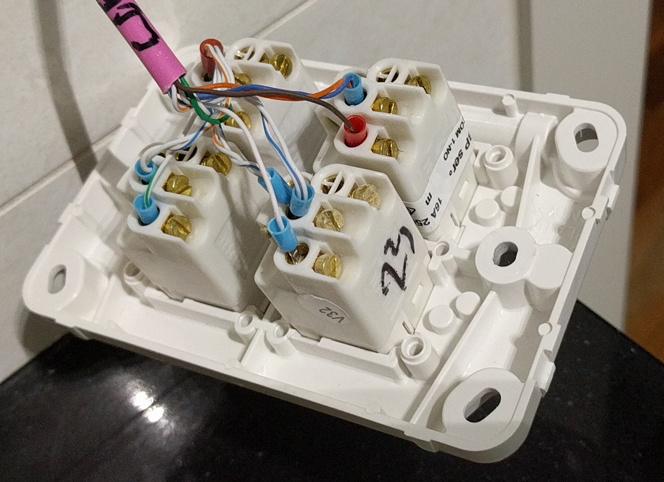
- Blue and orange +ve
- White-blue and white-orange -ve
- Green switch 1
- White-green switch 2
- Brown switch 3
- White-brown switch 4
Note that we’re using two wires together for +ve and -ve which helps increase capacity and reduce voltage drop (followed the Clipsal standard wiring of blue and orange pairs).
Later in Smart Mode, this Cat5e cable will be re-purposed as Ethernet for an Arduino or embedded Linux device.
Hallway Passive Infrared (PIR) Motion Sensors
I wanted the lights in the hallway to automatically turn on at night if someone was walking to the bathroom or what not.
- Upstairs hallway uses two 24V PIRs in parallel
- Either one turns on lights
- Connected to dumb mode network so fire relay as everything else
- Can be overridden by switch on the wall
- Adjustable for sensitivity, light level and length of time

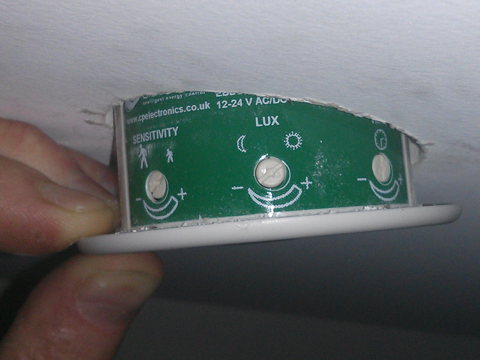
Tweaking the PIR means I have it only turning on the lights at night.
Dumb mode results
We have been using dumb mode for over a year now, it has never skipped a beat.
Now I just need to find the time to start working on the Smart Mode…

3 thoughts on “My Custom Open Source Home Automation Project – Part 3, Roll Out”
is this story over? i’m heart broken to not see part 4 available. i stumbled upon your blog, and my mind was blown when i realized some one else took basically the exact same route i had planned to take with the home i am building.
Is there any place i can read more information about your system? or is this blog as detailed as you’ve gotten? Please shoot me an email and let me know if a part 4 is in the works, of it there’s a forum or some place else you’ve posted even more technical reference.
thanks so much for your time
Brian
Hi, I am living in Australia as well and just wondering if you get a chance to update the Smart Mode? According to your blog it seems that you plan to have an adruino deployed to each room? How to do mount/maintan them if there is something wrong? (All electronics fails eventually) Would love to hear more about your home automation from you. Thanks!
Hi Tao, I am mostly using ESP8266 or ESP32 devices at the moment and use ESPHome to manage them. If they fail, it’s easy enough to flash a new one with the same code from my laptop using the same YAML definitions, then swap it out. I have a blog post about ESPHome here, if it helps https://blog.christophersmart.com/2020/03/31/defining-home-automation-devices-in-yaml-with-esphome-and-home-assistant-no-programming-required/